 AASTHA INTERNATIONAL
The Ultimate Guide to Hammer Unions: Types, Sizes, and Figures Explained
Discover everything you need to know about industrial hammer unions in this comprehensive guide. We break down the figure numbers, pressure ratings, sizing, and applications for oil and gas, mining, and beyond.
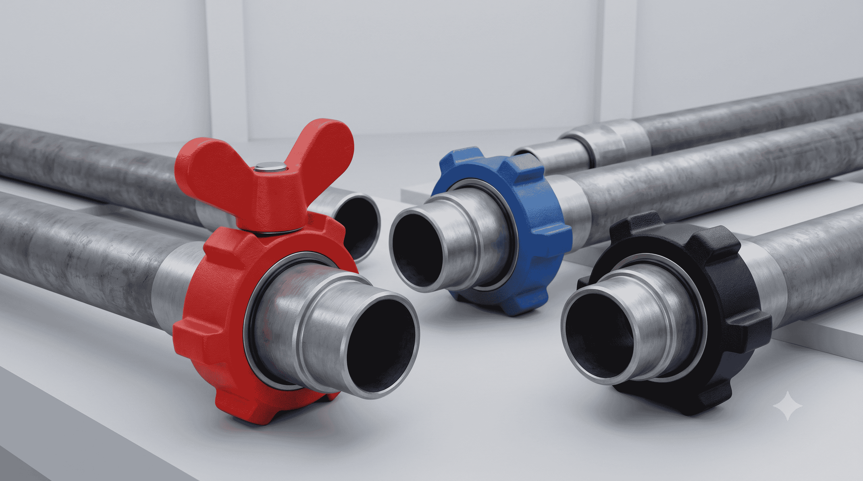
In the rugged world of industrial piping, where immense pressures, abrasive fluids, and harsh environments are just another Tuesday, standard threaded or flanged connections often fall short. When you need a high-pressure connection that can be made up quickly, torn down just as fast, and withstand the brutal realities of the field without leaking, you turn to one specific piece of hardware: the hammer union.
Whether you are rigging up a temporary flowline on an oilfield fracturing site, setting up dredging equipment, or managing heavy slurry lines in a mining operation, hammer unions are the undisputed champions of quick-connect pipe fittings.
But not all hammer unions are created equal. Walking into a supply yard and just asking for a "hammer union" is like walking into a car dealership and asking for "a vehicle." You need to know the specific pressure ratings, the color-coding, the end connections, and the "Figure" numbers to ensure you aren't creating a catastrophic safety hazard.
In this exhaustive guide, we are going deep into the mechanics of hammer unions. We will explore exactly what they are, how they work, the comprehensive list of Figure types, the available sizes, and how to select the right one for your specific industrial application.
What is a Hammer Union?
A hammer union is a heavy-duty, high-pressure pipe connector designed to join two pieces of pipe or temporary flow iron together. As the name suggests, it is designed to be tightened and loosened by striking it with a hammer (specifically, a sledgehammer or brass hammer).
Unlike traditional flanges that require careful alignment, multiple bolts, gaskets, and precise torqueing with wrenches, a hammer union can be made up by a single worker with a hammer in a matter of seconds. This makes them absolutely indispensable in industries where temporary piping systems must be rigged up and torn down frequently.
The Anatomy of a Hammer Union
A standard hammer union consists of three primary steel components, plus a sealing element (depending on the pressure rating):
The Thread Half (Male Sub): This is one end of the connection. It features external (male) coarse Acme threads on the outside and a machined seating surface on the inside face.
The Nut Half (Female Sub): This is the mating end of the connection. It has a smooth exterior and a machined face that perfectly matches the thread half.
The Hammer Nut: This is the massive, heavy steel ring that slides over the Nut Half. It features internal (female) Acme threads that mate with the Thread Half, and three prominent protruding "lugs" on the outside. These lugs are what the worker strikes with the hammer to tighten or loosen the union.
The Elastomer Seal (O-Ring or Lip Seal): While some low-pressure unions rely purely on metal-to-metal contact to create a seal, most medium-to-high-pressure unions feature a rubber O-ring or a resilient lip seal embedded in the face of the male sub. When the nut is tightened, it compresses this seal, creating a leak-proof barrier against high-pressure fluids and gases.
When these components are pushed together, the hammer nut is spun onto the thread half. As the lugs are struck with a hammer, the coarse Acme threads draw the two halves tightly together. The spherical radius of the male sub face is wedged into the conical face of the female sub. This ball-and-cone design, combined with the elastomer seal, is what allows hammer unions to hold back pressures exceeding 15,000 to 20,000 PSI.
Decoding the Figure System: Types of Hammer Unions
The industrial standard for identifying hammer unions is the Figure (Fig.) System. This system categorizes unions based on their pressure rating, the type of seal they use, and their intended application.
To make quick identification easy in the field, manufacturers also use a standardized color-coding system. The painted color of the nut and the subs immediately tells a trained eye exactly what Figure the union is, helping to prevent the dangerous mismatching of high-pressure lines.
Let's break down the most common hammer union figures from low pressure to ultra-high pressure.
Figure 50 (Low Pressure / Suction)
Pressure Rating: 500 PSI Cold Working Pressure (CWP)
Color Code: None (Usually unpainted or zinc-plated)
Application: Fig. 50 is a true low-pressure union, typically used for suction lines and low-pressure manifold applications. It is lightweight and relies primarily on a metal-to-metal seal. You will often see these in water lines or low-pressure mud lines where rapid assembly is needed but pressures are negligible.
Figure 100
Pressure Rating: 1,000 PSI CWP
Color Code: Yellow Sub / Black Nut
Application: This is a low-pressure union that utilizes a precision-machined metal-to-metal sealing surface. It is commonly used in general service applications, low-pressure water, and manifold lines. It is economical and robust for standard utility piping.
Figure 200
Pressure Rating: 2,000 PSI CWP
Color Code: Blue Sub / Gray or Blue Nut
Application: The Fig. 200 is arguably the most common general-utility hammer union in the world. It uses a strictly metal-to-metal ball-and-cone seal. Because it lacks an elastomer O-ring, it is highly durable and resistant to chemical degradation, making it excellent for air, water, oil, and gas lines where pressures do not exceed 2,000 PSI.
Figure 206
Pressure Rating: 2,000 PSI CWP
Color Code: Blue Sub / Gray Nut
Application: The Fig. 206 is nearly identical to the Fig. 200, with one critical difference: it incorporates an O-ring in the male sub. This O-ring provides a secondary soft seal alongside the primary metal-to-metal seal. The Fig. 206 is highly preferred over the 200 when dealing with corrosive or abrasive fluids, as the O-ring provides a more forgiving seal if the metal faces become slightly scratched.
Figure 207
Pressure Rating: 2,000 PSI CWP
Color Code: Blue Sub / Gray Nut
Application: This is a "Blanking" union. Instead of having an open bore for flow, one side is completely capped off (a blanking plug). It is used to quickly and securely cap off the end of a piping run, seal a manifold, or close off a tank. It utilizes an O-ring seal to ensure zero leakage.
Figure 211
Pressure Rating: 2,000 PSI CWP
Color Code: Gray Sub / Blue Nut
Application: Similar to the 200 series but designed as an insulating union. It features laminated phenolic rings that provide electrical insulation between the two halves of the pipe. This is vital in preventing electrolytic corrosion (galvanic corrosion) in pipelines, especially in marine environments or chemical plants.
Figure 300
Pressure Rating: 2,000 PSI CWP
Color Code: Yellow Sub / Black Nut
Application: Flat-faced union. Unlike the standard ball-and-cone design, the Fig. 300 uses a flat face with an O-ring. This flat design means the pipe doesn't need to be sprung apart or pulled back to remove the union; it can slide out laterally. It is ideal for tight spaces or rigid piping installations where lateral movement is restricted.
Figure 400
Pressure Rating: 4,000 PSI CWP
Color Code: Red Sub / Black Nut
Application: The 400 series introduces higher pressure capabilities. It utilizes a precision metal-to-metal seal and is often found in rotary hose connections, mud pump discharge lines, and medium-pressure manifold applications. Its heavier wall thickness allows it to handle the 4,000 PSI threshold safely.
Figure 600
Pressure Rating: 6,000 PSI CWP
Color Code: Silver Sub / Black Nut
Application: Used extensively in well servicing and drilling. The Fig. 600 relies on a bronze seat insert to provide the primary seal. This bronze-to-steel contact is highly effective at sealing but requires a bit more care to avoid galling or damaging the softer bronze insert.
Figure 602
Pressure Rating: 6,000 PSI CWP
Color Code: Orange Sub / Black Nut
Application: The Fig. 602 is a staple in the oil and gas industry, specifically for mud lines, cementing, and well servicing. Unlike the 600, it uses a replaceable lip-type elastomer seal ring (often made of Nitrile or Viton) embedded in the female sub. This lip seal provides excellent protection against high-pressure abrasive slurries, protecting the metal sealing faces from erosion.
Figure 1002
Pressure Rating: 10,000 PSI CWP
Color Code: Red Sub / Blue Nut
Application: Entering the high-pressure realm, the Fig. 1002 is designed for cementing, fracturing, acidizing, and choke-and-kill lines. It utilizes a resilient, replaceable lip-type elastomer seal. The heavy-duty forging of the 1002 ensures it can withstand severe shock, vibration, and abrasive fluids common in well stimulation.
Figure 1003
Pressure Rating: 10,000 PSI CWP
Color Code: Yellow Sub / Black Nut
Application: This is a specialized union designed for misalignments. Often called a "misaligning union," the ball-and-cone mechanism is exaggerated, allowing for up to 7.5 degrees of angular misalignment (15 degrees total). It is a lifesaver in the field when rigid pipes don't line up perfectly, preventing operators from having to force or bend heavy iron to make a connection.
Figure 1502
Pressure Rating: 15,000 PSI CWP
Color Code: Red Sub / Blue Nut (Though often completely Red or Blue depending on the manufacturer's sour-service designation)
Application: The undisputed king of the oilfield. The Fig. 1502 is the industry standard for high-pressure hydraulic fracturing (frac iron), severe cementing, and ultra-high-pressure manifolding. It uses a specialized replaceable lip seal ring that prevents abrasive high-pressure fluids from eroding the metal-to-metal seal. If you see high-pressure iron rigged up on a modern well pad, 99% of the time, it is joined by Fig. 1502 unions.
Figure 2002 / 2202
Pressure Rating: 20,000 PSI CWP
Color Code: Green Sub / Green Nut
Application: These are ultra-high-pressure unions. They are heavily forged and noticeably bulkier than standard unions. They are reserved for extreme pressure well stimulation, deepwater operations, and extreme choke-and-kill lines. They utilize advanced elastomer compounds and heavy-wall alloy steel to safely contain pressures that would burst standard piping.
Standard Hammer Union Sizes and End Connections
Understanding the Figure type and pressure rating is only half the battle. You also must specify the nominal size and the type of end connection required to attach the union to your piping system.
Standard Sizes
Hammer unions are manufactured to correspond with standard nominal pipe sizes (NPS). The most common sizes found in industrial supply yards are:
1 inch
2 inch (The most common size for general flowlines)
3 inch (Common in high-volume frac and cementing lines)
4 inch (Common in suction and high-volume discharge)
5 inch
6 inch
8 inch
10 inch
12 inch (Primarily for low-pressure, high-volume applications like dredging or mud suction)
Types of End Connections
How you attach the hammer union to your pipe is critical for the overall integrity of the system. There are three primary end connections available:
1. Threaded Ends (API Line Pipe / NPT)
Threaded unions feature internal female threads on both the Thread Half and the Nut Half. The pipe is simply screwed into the union using thread sealant (pipe dope or Teflon tape).
Pros: Easy to install in the field; requires no welding equipment.
Cons: Threads create stress risers. Threaded connections are prone to leaking at extreme pressures or under heavy vibration. They are generally restricted to lower pressure figures (like Fig. 200/206) and smaller pipe sizes.
2. Butt-Weld Ends
A butt-weld union has flat, beveled ends. The pipe is aligned directly against the end of the union, and a full-penetration weld is made around the circumference.
Pros: Provides the strongest, most leak-resistant connection possible. It eliminates the stress risers associated with threads. Butt-weld is the mandatory standard for high-pressure applications (like Fig. 1502 operating at 15,000 PSI).
Cons: Requires a certified welder, welding equipment, and often post-weld heat treatment or non-destructive testing (NDT), making field installation slower and more expensive.
Important Note: When ordering butt-weld unions, you must specify the pipe schedule (e.g., Schedule 40, Schedule 80, XXH - Double Extra Heavy). The bore of the union must perfectly match the internal bore of the pipe to ensure a smooth flow transition and prevent turbulence and erosion.
3. Socket-Weld Ends
In a socket-weld union, the end of the union features a machined step or "socket." The pipe slides into this socket, and a fillet weld is applied around the outside edge where the pipe meets the union.
Pros: Easier to align than a butt-weld. Stronger and more leak-proof than threaded ends.
Cons: The gap at the bottom of the socket can cause fluid turbulence and trap corrosive materials (crevice corrosion). They are generally limited to smaller pipe sizes (under 2 inches) and medium pressures.
Materials and Service Environments: Standard vs. Sour Service
Hammer unions are typically forged from high-quality carbon steel or alloy steel (such as AISI 4130). Forging provides a much denser, stronger, and more uniform grain structure than casting, which is essential for components subjected to high impact (hammering) and extreme internal pressures.
However, the specific metallurgy must be matched to the environment—specifically, whether the fluid contains Hydrogen Sulfide ($H_2S$).
Standard Service
Standard service unions are designed for relatively benign fluids: fresh water, drilling mud, cement, oil, and non-corrosive natural gas. They are heat-treated to achieve maximum tensile strength and hardness, allowing them to withstand high pressures and rough handling without deformation.
Sour Service ($H_2S$) / NACE MR0175
When natural gas or crude oil contains Hydrogen Sulfide ($H_2S$), it is considered "sour." $H_2S$ is highly toxic and corrosive. More dangerously, it causes a phenomenon known as Sulfide Stress Cracking (SSC) in high-strength steels.
If standard service, high-hardness steel is exposed to $H_2S$ under pressure, the metal absorbs hydrogen atoms, becomes brittle, and can violently shatter without warning.
To prevent this, hammer unions intended for sour service must comply with the NACE MR0175 standard.
Metallurgy: The steel is specially heat-treated (tempered) to maintain a maximum hardness of 22 HRC (Rockwell C). This lower hardness makes the steel ductile enough to resist sulfide stress cracking.
Pressure Derating: Because the metal is softer, sour service unions must be physically heavier (thicker walls) to hold the same pressure, or their pressure ratings must be reduced. For example, a standard Fig. 1502 is rated for 15,000 PSI CWP. A sour service Fig. 1502, made from NACE-compliant softer steel, is physically identical on the outside but is typically derated to 10,000 PSI CWP to account for the altered metallurgy.
Identification: Sour service unions are usually painted olive green or stamped clearly with "SOUR" or "NACE" to differentiate them from standard service unions.
The Mechanics of the Seal: Why They Don't Leak
Understanding how a hammer union achieves a zero-leak seal at 15,000 PSI is crucial for proper maintenance and operation.
The Spherical Interface: The metal-to-metal seal is not flat. The male sub features a convex, spherical radius, while the female sub has a concave, conical taper. When the nut pulls them together, this ball-and-cone geometry forces the two surfaces to mate perfectly, even if the pipes are slightly out of alignment.
The Acme Thread Advantage: Hammer nuts utilize coarse, heavy-duty Acme threads rather than standard V-threads. Acme threads are incredibly strong and resistant to stripping, cross-threading, and damage from dirt or sand. The steep angle of the thread allows the nut to pull the subs together with massive axial force with every blow of the hammer.
Elastomer Compression: In unions like the Fig. 1502 or 602, the metal-to-metal seal is the primary load-bearing surface, but the true fluid seal is provided by the elastomer lip seal. As the metal faces come together, they compress the rubber seal into its machined groove. The internal pressure of the fluid actually forces the lip of the seal outward against the steel, meaning the seal gets tighter as the pressure increases.
Safety, Installation, and Maintenance Best Practices
Hammer unions are inherently safe when used correctly, but they handle enough pressure to cause catastrophic injury or death if misused. Strict adherence to safety protocols is non-negotiable.
1. The Danger of Mismatched Components
Never mix and match halves of different figures. While a Figure 602 nut might physically thread onto a Figure 1502 male sub, the sealing faces and pressure tolerances are entirely different. If pressurized, a mismatched union will either leak violently or mechanically separate like a projectile. Always verify the Figure number, size, and color code on both halves before making a connection.
2. Proper Hammering Technique
Tightening a union requires striking the lugs of the nut.
Always use a brass or lead hammer when working in potentially explosive environments to prevent sparking.
Do not over-hammer. Once the metal-to-metal faces are seated, further hammering only damages the lugs and stretches the threads, without improving the seal. The old oilfield adage is "make it up tight, but don't beat it to death."
When loosening, ensure all pressure has been completely bled from the line before striking the lug. Striking a pressurized union can cause the nut to violently spin off.
3. Inspection and Maintenance
Hammer unions take a beating. They are thrown in the mud, tossed into truck beds, and hammered constantly.
Visual Inspection: Before every makeup, inspect the male and female sealing faces. Any deep scratches, gouges, or galling on the ball-and-cone surfaces will cause a leak. Minor scratches can sometimes be polished out with emery cloth, but severe damage requires replacing the sub.
Thread Inspection: Check the Acme threads inside the nut and on the male sub. Look for flat spots, cracks, or rolled threads.
Seal Replacement: The elastomer seal (O-ring or lip seal) is a wear item. Inspect it for cuts, tears, extrusion, or chemical degradation (swelling). When in doubt, throw it out and insert a fresh seal. Never reuse a heavily deformed seal.
Non-Destructive Testing (NDT): For high-pressure iron (like Fig. 1502 used in fracking), industry standards recommend annual ultrasonic wall-thickness checks and magnetic particle inspection (MPI) to detect microscopic fatigue cracks in the forgings.
Applications Across Industries
While born in the oil patch, the reliability and speed of hammer unions have seen them adopted across a wide array of heavy industries.
Oil and Gas Exploration and Production This is the primary domain of the hammer union. They are used to assemble temporary flowlines for hydraulic fracturing, cementing operations, acidizing, well testing, and choke-and-kill manifolds on drilling rigs. The ability to rig up thousands of feet of high-pressure 1502 iron in a single day is entirely dependent on hammer unions.
Mining and Dredging In operations that pump heavy, abrasive slurries (mixtures of water, rock, and sand), operators use large-diameter, low-pressure unions (like the Fig. 50 or 100 in 8" to 12" sizes). The quick-connect nature allows operators to quickly rotate or replace sections of pipe that have been eroded by the abrasive slurry.
Chemical and Petrochemical Processing When chemical plants undergo maintenance shutdowns (turnarounds), temporary piping and bypass lines must be installed quickly. Fig. 200, 206, and 300 unions are frequently used to route nitrogen, cooling water, and chemical wash lines efficiently without having to weld temporary flanges.
Agriculture and Irrigation Large scale irrigation systems and water transfer lines often utilize aluminum or lightweight steel hammer unions to quickly connect and disconnect massive water hoses across vast fields, allowing for rapid deployment and storage of equipment.
Conclusion
The hammer union is a masterpiece of robust industrial engineering. By combining the mechanical advantage of coarse Acme threads with the hydrodynamic perfection of ball-and-cone seating surfaces, it provides an unparalleled combination of speed, strength, and reliability.
Whether you are dealing with a low-pressure water line requiring a quick-disconnect Figure 100, or commanding a 15,000 PSI hydraulic fracturing operation reliant on the rugged Figure 1502, understanding the nuances of the Figure system, sizing, and material limits is paramount.
By respecting the pressure ratings, diligently inspecting the sealing surfaces, and strictly avoiding mismatched components, industrial operators can ensure that these vital connections perform safely and flawlessly in the harshest environments on earth.